When you first unroll a set of plans for a build or site job, it usually feels like you're looking at a foreign language. If you're trying to learn how to read blueprints for an excavation project, start with the sheet title, legend, and scale, then focus on the site, grading, foundation, and utility plans so you can understand where the work happens, how deep it goes, and where water needs to move.
If you're a homeowner or first-time developer, the confusion is normal. You don't need to read every sheet like an engineer, but you do need enough understanding to catch issues before they turn into excavation changes, drainage problems, or foundation delays.
That matters most at the beginning. Once digging starts, even a small misunderstanding on paper can turn into extra hauling, regrading, trench relocation, or a stop-work conversation nobody wants. If you need a basic overview of how excavation fits into the construction process, this explanation of what excavation means in construction is a good starting point before you study the plans themselves.
Quick Answer
To learn how to read blueprints for site work, check the title block, revision block, legend, and scale first. Then go to the sheets that matter most for excavation: the site plan, grading plan, foundation plan, and utility plan. If you can read contours, spot elevations, and drainage notes, you'll understand most of what controls the work in the field.
Introduction
A rolled-up plan set lands on your table, and every page is covered with lines, symbols, abbreviations, and notes in tiny print. Most owners look at it for about two minutes, then hand it back to the contractor and hope everyone else has it handled.
That trust is understandable, but blind trust isn't a good system for site work. Excavation happens early, and it affects nearly everything that comes after it: foundation elevation, driveway slope, drainage, utility trenching, and how the finished yard performs in winter.
Blueprint reading has a long history in construction. The cyanotype process developed by Sir John Herschel in 1842 became the basis for blueprint reading, and the basic habits it created, reading scales, symbols, plans, elevations, and sections, still carry straight into modern site work today (VDCI blueprint reading overview). The tools are newer now, but the discipline is the same.
For a site project in Sonoma County or Monterey County, start with three things before you study any detail. Read the title block so you know what sheet you're holding and whether it's current. Read the legend and notes so the symbols and abbreviations mean something. Then find the scale and north arrow, because if you don't know orientation and drawing scale, the rest of the sheet can fool you fast.
What to Look for First on Any Blueprint
On a first review, owners usually stare at the center of the page. For site work, that is rarely the best place to start. The border of the sheet tells you whether the drawing is current, what discipline produced it, and whether it applies to the work you are about to pay for.
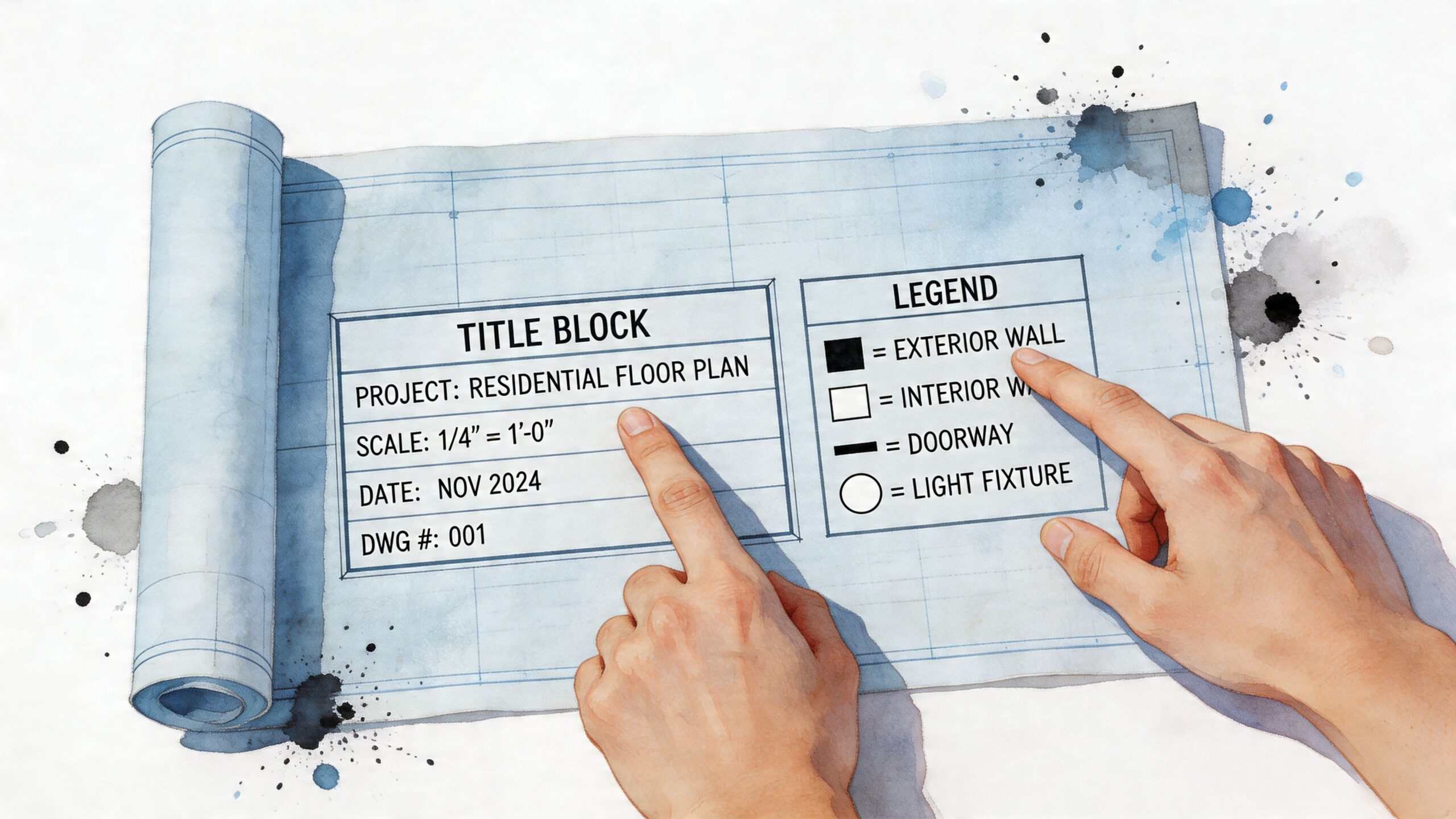
Read the title block before the drawing
The title block is usually at the bottom right. It identifies the project, address, sheet title, date, scale, and the architect, engineer, or civil designer responsible for that page.
I check that box first because it answers the questions that affect field decisions. Are you holding the grading plan or a utility plan? Is it the latest issue, or an earlier submittal that should have been pulled from the set? If the sheet title says "conceptual" or "not for construction," that changes the whole conversation.
For excavation work in Sonoma or Monterey County, this matters fast. A homeowner may be looking at a nice clean site plan while the crew is supposed to build from a revised civil sheet with different pad elevations or drainage notes. If those two pages do not match, the dirt still gets moved, and fixing it later is expensive.
Check the revision block next
The revision block shows what changed and when. On a good set, it also points you to revision clouds or notes so you can see the exact areas that moved.
That small box can save a lot of confusion.
A revision might shift a retaining wall, change footing dimensions, raise finish floor elevation, or reroute a storm drain line. Those are not drafting details. They affect cut and fill quantities, trench depths, export costs, and whether water ends up where the engineer intended.
If the owner, engineer, and contractor are not all looking at the same revision, expect delays. I have seen jobs lose days over an old sheet that stayed in the truck while the updated one sat in someone's inbox.
Use the legend and notes like job instructions
The legend defines symbols, line types, hatching, and abbreviations. The notes tell you how the designer wants the work built, verified, or coordinated in the field.
Common abbreviations include UNO for "unless noted otherwise" and VIF for "verify in field." Those are easy to skip, but they carry real responsibility. If a note says to verify an existing invert elevation before tying in a drain, that means the drawing is giving you a target, not a guarantee.
For site development, notes often matter more than the linework itself. A pipe may be drawn in one location, but the note may specify minimum slope, bedding, compaction, or cleanout spacing. A hatch may mark structural fill, but the note may limit where that fill can be used under slabs, pavements, or wall backfill.
Confirm orientation and scale
After that, check the north arrow and the scale.
The north arrow helps you compare the page to the actual lot. That matters if you are standing on a sloped parcel trying to understand where runoff leaves the site, how the driveway approaches the road, or which side yard has enough room for equipment access.
Scale tells you how to read distance on paper. A detail might be drawn at 1 inch equals 10 feet, while another sheet in the same set uses a different scale entirely. That is where owners get tripped up. They measure one plan with the assumptions from another and come away thinking a swale, footing offset, or trench run is larger or smaller than it really is.
Never assume all sheets use the same scale. Check each one.
Find the sheet index before you chase details
On larger plan sets, the sheet index keeps the review organized. It shows which sheets are civil, structural, architectural, or general, and it helps you find the pages that control the ground instead of the building finishes.
A simple discipline code can save time. C often marks civil sheets, S marks structural, A marks architectural, and G marks general sheets. The exact lettering can vary by designer, but the idea is the same. Use the index to follow one issue across the set.
For excavation, that means checking whether the grading sheet agrees with the foundation plan, whether the utility plan conflicts with footing locations, and whether general notes add requirements the drawing does not show clearly. A blueprint set is not one picture. It is several layers of instructions, and the first pass should tell you which pages deserve your full attention.
The Key Blueprint Types for Excavation and Site Work
Generic blueprint guides spend a lot of time on doors, windows, and room layouts. For site work, those aren't the pages that usually cause trouble first. The sheets that matter most are the ones that control the ground itself.
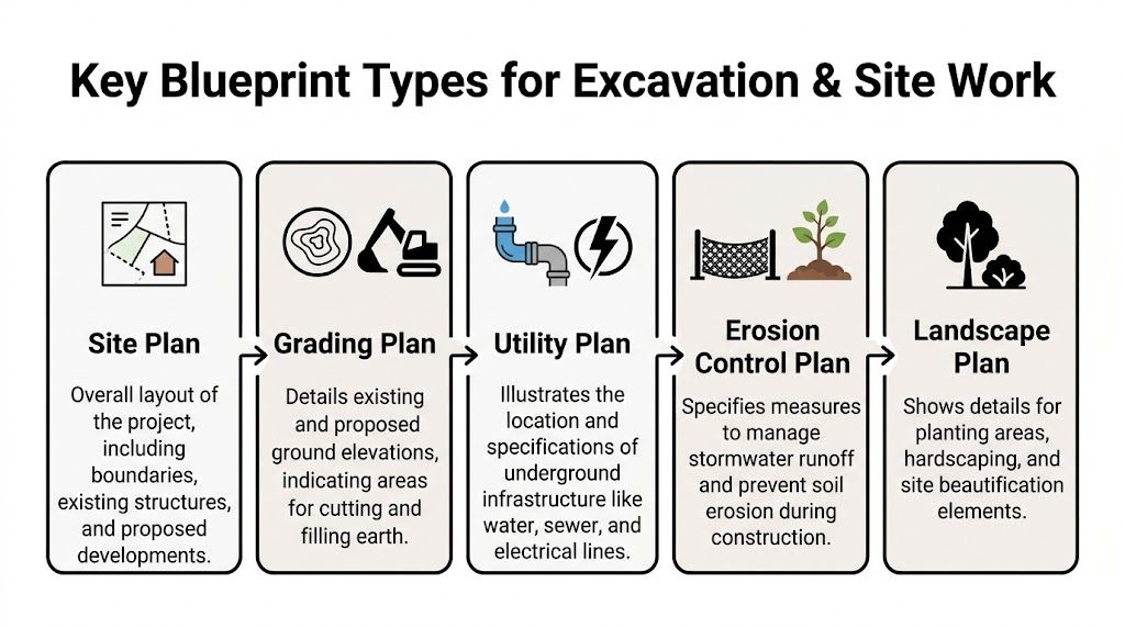
Site plan
The site plan is the broad view. It shows the parcel boundary, setbacks, building footprint, access points, easements, and the relationship between proposed work and existing conditions.
This is usually the sheet I want a property owner to understand first. If the building sits tighter to one property line than expected, if access for equipment is limited, or if the driveway alignment doesn't make sense, the site plan usually reveals it.
If you want a clearer overview of what belongs on this type of drawing, this guide on what a site plan is and who can help make one lays that out in practical terms.
Grading and drainage plan
For excavation, the grading and drainage plan is often the most important sheet in the whole set. It shows existing grade, proposed grade, contour lines, spot elevations, drainage direction, swales, inlets, and sometimes retaining features or benching notes.
Understanding blueprints is critical for hillside jobs. According to reports from the American Society of Civil Engineers, as many as 40% of hillside construction failures in California can be traced back to misread site plans (ASCE, 2024). On sloped property, you can't afford to skim this sheet.
A clean-looking grading plan on paper can still be unrealistic in the field if the slope transitions are too abrupt or drainage doesn't have a clear path out.
What works is reading the contours and spot grades together. What doesn't work is looking only at the building pad and ignoring where the water goes after the pad is cut.
Foundation plan
The foundation plan tells you where the structural support lands and what the excavation has to provide. You'll usually find footing layout, dimensions, step footings, wall lines, and references to sections or structural details that explain depth and reinforcement requirements.
This sheet matters because excavation isn't just about digging a hole that matches the footprint. It's about matching the structural intent. On sloped sites, footing transitions and stepped conditions need close attention. If you want a deeper design perspective, these notes on shallow and deep foundation designs are useful for understanding why one foundation approach may be chosen over another.
Utility plan
The utility plan controls trenching and conflict avoidance. It shows where sewer, water, storm drainage, and sometimes electrical or communication runs are expected to go.
For a homeowner, this sheet often answers two practical questions. Where will the trenches run, and will any line conflict with the footing, driveway, drainage system, or existing structures? A utility route that looks simple on one sheet can become complicated once you compare it with foundation and grading sheets side by side.
Erosion control and landscape sheets
These aren't always the first sheets people think of, but they matter. Erosion control plans show temporary and permanent measures to manage sediment and runoff during construction. Grounds plans can affect finish grading, drain placement, tree protection, and hardscape transitions.
On a simple flat lot, these sheets may be straightforward. On a hillside lot or a tight infill site, they can change how early grading and site protection need to be sequenced.
What each sheet should answer
If you're trying to sort the plan set fast, use these questions:
- Site plan tells you where everything sits.
- Grading plan tells you how the ground changes.
- Foundation plan tells you what has to be supported and excavated precisely.
- Utility plan tells you where trenching and underground coordination happen.
- Erosion control plan tells you how the site is protected while work is underway.
If one of those answers is missing or vague, stop and ask. That's usually where change orders begin.
How to Read Blueprint Symbols, Contours, and Elevations
A set of site plans usually starts making sense the moment you stop reading it like a drawing and start reading it like dirt moving on a real lot. On excavation work, symbols and elevation notes are not decoration. They tell you where the cut goes, where the fill goes, where water ends up, and whether the foundation area is buildable.
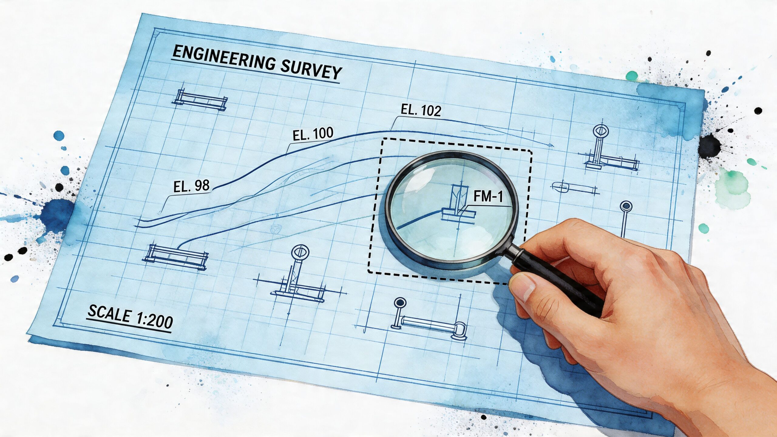
Start with contour lines
Contour lines show the shape of the ground at equal elevations. Tight contours mean the grade changes fast. Wide spacing means the slope is flatter and easier to work with.
For a homeowner or first-time developer, the first question is not what the lot looks like on paper. The first question is whether the grading plan creates a site that drains properly and can be excavated without forcing awkward slope cuts, retaining walls, or extra export. On hillside parcels in Sonoma or Monterey County, that difference matters early.
Look at both existing and proposed contours together. That comparison shows where the engineer expects cut and fill. If the proposed contours push water toward the house, flatten a natural drain path, or create steep transitions near driveways or pad edges, ask about it before work starts.
Read spot elevations like checkpoints
Spot elevations are fixed numbers tied to specific points. You'll usually find them at pad corners, swales, top and toe of slope, flow lines, drainage structures, and driveway breaks.
Those numbers should agree with each other. If the front corner of a pad is higher than the rear corner, there should be a reason. Sometimes the reason is drainage. Sometimes it is a split-level condition. Sometimes it is a coordination mistake between sheets.
That is why I tell owners to stop on any number that affects water, access, or foundation depth.
A few tenths of a foot can change how runoff behaves around a slab or whether a drain inlet works in the field.
Understand line types and abbreviations
Lines carry instructions, but only if you read them against the legend. A dashed line might be an existing utility, an overhead element, or something hidden below finish grade. A hatch pattern might mark concrete, engineered fill, or an area with a different treatment requirement.
Here are the symbols and line types that usually matter most during site work review:
| Symbol / Line Type | What It Means |
|---|---|
| Solid line | Usually a visible or proposed feature |
| Dashed line | Often an existing, hidden, or overhead feature, depending on the legend |
| Contour line | Connects equal elevations to show land form |
| Spot elevation | Shows a precise elevation at one point |
| Property line | Marks the legal lot boundary |
| Utility line symbol | Identifies sewer, water, storm, or other underground service |
| Slope arrow | Shows intended drainage direction |
| Hatch pattern | Marks a material or area type such as concrete, paving, or fill |
| Grid reference | Helps locate an area within a larger plan set |
| Section callout | Sends you to another sheet for a cut-through detail |
If you want a companion guide for the building-side notation that often shows up beside site sheets, this overview of how to read architectural drawings is useful.
Use the scale carefully
Printed dimensions and written notes control the work. The scale is a checking tool.
That distinction saves people from expensive assumptions. If the drawing says one thing and your scale suggests another, trust the stated dimension and ask for clarification. Plans are often printed at different sizes, and reduced plan sets can throw off scale reading right away.
Use scale to estimate spacing, compare distances, and get oriented. Do not use it to guess footing widths, utility clearances, or setback dimensions that should already be called out.
Pay attention to the notes tied to grading and foundation work
Generic blueprint advice often falls short. For site development, the problem is not just identifying a symbol. The problem is understanding how one note affects excavation quantity, drainage behavior, and foundation prep.
I watch for footing or overexcavation references hidden in details instead of shown clearly on the main plan. I check whether drain inlets have invert elevations that work with the proposed surface grades. I compare utility crossings with footing edges, retaining features, and trench spacing. I also look at fill and compaction notes to see whether they are tied to a specific area or written so generally that the field crew is left guessing.
Plans can look clean and still leave real field questions unanswered. Those are the jobs that stall once equipment is on site.
Build the full ground picture
Good plan reading comes from combining the symbols into one physical story of the lot. By the time you're done reviewing the sheet, you should be able to answer a few plain questions without guessing:
- Where does the finished pad sit relative to the surrounding grade?
- Which areas are cut, and which are fill?
- How will water leave the site or move into approved drainage points?
- Are driveway slopes and transitions practical for vehicles and equipment?
- Do the grading, utility, and foundation sheets support the same finished elevations?
That first question matters more than many owners realize. If you want a practical explanation of how the graded surface under the structure is supposed to function, this guide on what a building pad is helps connect the plan notes to actual excavation work.
If a plan set cannot answer those questions clearly, it needs another review. In excavation, confusion usually shows up first in drainage, slope layout, or foundation prep. That is where delays and change orders start.
Common Blueprint Mistakes That Cause Project Delays
A project can look ready on paper and still break down the first morning the excavator shows up. I see that happen when the plans leave too much unresolved between grading, drainage, utilities, and foundation work.
Conflicts between sheets
The most expensive blueprint mistakes are often coordination mistakes. A grading sheet may show a clean drainage swale, while the utility plan puts a line through it. A structural detail may call for footing excavation that clashes with a storm drain route or a retaining element. On a house pad, those conflicts do not stay on paper for long. They turn into stoppages, field calls, and revised layouts.
That does not always mean the engineer or designer did poor work. It often means different parts of the plan set were prepared at different times, and nobody fully checked how they come together in the dirt.
Grading that works on paper but creates field problems
Some grading plans meet the design intent and still create trouble during construction. I watch for driveway transitions that are too abrupt, drainage flow lines that are not clear enough to stake, and slope shapes that leave very little room for equipment, spoils, or safe trenching.
This comes up often on tighter lots in Sonoma County and on sloped sites in Monterey County. The elevations may be mathematically correct, but the sequence of excavation, export, backfill, compaction, and drainage installation is still awkward. That slows the job down even before you get to inspections.
Notes that leave too much open
Vague notes cause more trouble than many owners expect. "Verify in field" has its place, but if the plans rely on it too often, the crew is left making judgment calls that should have been settled before mobilization. Missing outlet information, references to details that are not included, and general compaction notes with no clear area of application are all warning signs.
Delays and disputes often begin at that point.
If you want a good owner-level example of how plan assumptions turn into real site issues, read this piece on what Santa Rosa homeowners get wrong about site plans.
A short review checklist before work starts
Use these questions before excavation starts, not after equipment is scheduled.
- Are all sheets from the same revision set with a current approval date?
- Do the grading, utility, and foundation plans agree on elevations, alignments, and clearance points?
- Is stormwater discharge clearly shown from the pad, driveway, and uphill drainage areas?
- Are footing steps, trench locations, and over-excavation notes fully defined for the actual site conditions?
- Do any notes shift design decisions to the field crew instead of resolving them in the plans?
A clear set of plans saves time in the field. A vague set usually costs time, money, or both.
A Checklist for Meeting with Your Contractor or Engineer
Bring a printed set, a highlighter, and a pen. Digital plans are fine, but paper still makes review easier when several people are standing around the same sheet.
Use this list to keep the meeting practical.
- Confirm the plan version. Ask everyone to identify the latest revision date and sheet set being used.
- Verify the grading intent. Ask where cut and fill occur, how final drainage leaves the site, and whether any slope transitions need special handling.
- Check utility conflicts. Ask whether sewer, water, storm, and other lines cross footing zones, retaining areas, or future paving.
- Pin down foundation-related excavation. Ask which details govern footing depth, step locations, and over-excavation if unsuitable soil is found.
- Ask what must be verified in field. If the plans use VIF notes, ask who is responsible for checking those conditions and when.
- Clarify approvals and sequencing. If you're still in preconstruction, this guide on how to get your site plan approved faster helps you understand where paperwork and field planning need to line up.
You don't need to sound technical in that meeting. You need clear answers. If the team can explain the plan in plain language, that's a good sign the project is ready.
Frequently Asked Questions About Reading Blueprints
Do I need special software to learn how to read blueprints
No. You can learn a lot from printed sheets or standard PDF plan sets. Software helps with zooming, overlays, and markup, but the basic skill is still knowing how to read the title block, notes, scale, and key site sheets.
What's the first sheet I should study for an excavation project
Start with the site plan, then move to the grading plan. After that, review the foundation and utility sheets together so you can see where excavation, trenching, and structural support interact.
What's the difference between an architect's scale and an engineer's scale
They measure differently and are used on different kinds of drawings. For most owners, the important part isn't mastering both right away. It's checking what scale the sheet uses before trying to measure anything.
What does VIF mean on a blueprint
It means verify in field. That tells the contractor or design team that an existing condition needs to be confirmed on site instead of assumed from the drawing alone. When you see it, ask who is verifying it and when.
Can I review my own plans, or should I leave that to the professionals
You should absolutely review your own plans. You don't need to replace the engineer or contractor, but you should understand enough to ask questions about drainage, elevation changes, utility routing, and foundation layout. That usually leads to better conversations and fewer surprises.
How expensive can blueprint mistakes become
The cost depends on where the mistake shows up. A small notation issue caught early may only mean a quick clarification. A grading or utility conflict discovered after excavation starts can affect schedule, hauling, trenching, and follow-on trades, so it's always cheaper to catch confusion before mobilization.
Ready to Start Your Project with Confidence?
When you learn how to read blueprints, you're not trying to become a designer overnight. You're putting yourself in a position to ask better questions, catch basic problems early, and understand whether your site work is being planned in a way that makes sense for the ground, drainage, and foundation.
That kind of clarity matters on every project, especially when you're dealing with slopes, utilities, or tight lot conditions on the California Central Coast.
Sources
VDCI. "What Is Blueprint Reading?" 2024. https://vdci.edu/learn/blueprint-reading/what-is-blueprint-reading
BigRentz. "How to Read Construction Blueprints." 2023. https://www.bigrentz.com/blog/construction-blueprints
Advanced Building Corporation. "Construction Blueprint Reading Guide." 2024. https://www.advancedbuildingcorporation.com/blog/construction-blueprint-reading-guide/
American Society of Civil Engineers reference cited in NABTU course materials. "8HR Blueprint Reading Principles." 2024. https://nabtu.personalearning.com/warehouse/nabtu/documents/course/387/8HR%20Blueprint%20Reading%20Principles%20-%20INST%20PPT.pdf
If you're planning excavation, grading, drainage, foundation work, or underground utility work in Sonoma County, Monterey County, or the California Central Coast, DW Excavation, LLC can review your plans with you and talk through the site conditions before work begins. For a free estimate or site consultation, call (707) 601-9091, visit 470a Caletti Avenue, Windsor, CA 95492, or head to dw-excavation.com.